Driving a Viewfinder from 1982
Last summer I managed to come across a fantastic new toy: a 1982 JVC video camera, with a pretty excellent 10-100mm f/1.6 lens, which became part of my microscope project.
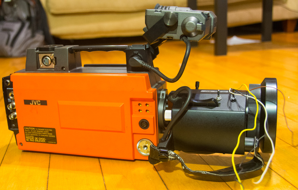
Recently, I decided to play around with the remaining pieces of the camera, to see if I could learn any more from it. Specifically, I decided to see if I could drive the viewfinder as a tiny analog television screen.
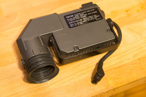
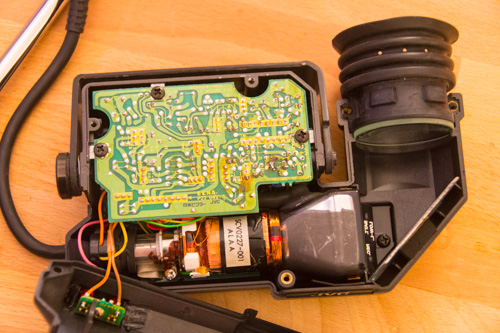
Separating the viewfinder from the camera was easy (praise be to 1980s electronics!), as was opening it up to take a look at the innards:
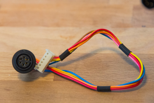
Powering and controlling the viewfinder could have involved a mess of cutting, soldering, and splicing to connect the relevant wires, but I was saved again by the beautiful simplicity of 80s electronics. The viewfinder came with a slightly obscure circular connector:
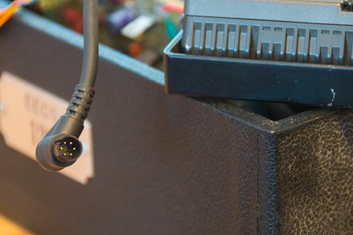
But, of course, the camera came with a perfectly compatible connector, which was trivial to remove once I’d opened up the case, and which even broke out into a standard 0.1 inch female header:
Wiring up the viewfinder was just a matter of deciding which pins were which and then providing the appropriate signals. The pins were only labeled with letters A-F, with no indication of ground, power, data, etc. I found a post on fixya which seemed to describe my connector exactly:
6 pin connector and pins marked A to F?
A: Tally
B: 12V
C: Gnd
D: Vid. Gnd.
E: Video
F: Battery alarm
With no indication that this would be correct for my particular camera, I decided to do my best to evaluate this pinout before providing any power. First, I determined that pins C and D (ground and video ground) were indeed connected together inside the viewfinder, as expected, and they were also connected to the grounds of the recording LEDs through a small resistor, which again made sense. With ground identified, I was reasonably confident that I could power the viewfinder without destroying it. As a bonus confirmation, pin B, supposedly the +12V power, had a red wire connected to it, which made me slightly more confident that it was indeed the power line.
With the pins identified, I attached a 12V power supply to pins B and C, connected ground to pin D, and ran a single wire to pin E (video in). After a few seconds, the familiar high-pitched whine of a CRT started, and the viewfinder screen began to glow along a narrow band across the middle of the screen. Touching the video input wire with my finger to provide some electrical noise generated tons of noise in the displayed video, which confirmed that I had wired everything up correctly.
To test the viewfinder, I wired the composite video output from my Raspberry Pi into the video input and ground of the viewfinder. And it (almost!) worked. Unfortunately, the resulting image was a mess, with the image never leaving the narrow band in the center of the screen:
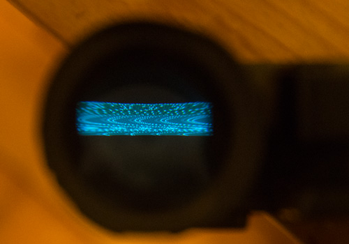
The fact that the image was badly squashed into the center band with or without video input, combined with the fact that the camera was broken when I received it, led me to believe that the viewfinder was most likely damaged. Alas, repairing it would be a whole other project, and not one for today.
Instead, I decided to complete my dissection of the entire camera, to see what fun parts would lurk within.
Dissecting a 1982 Video Camera
The prevailing theme of this project was “gosh, 80s electronics are fabulously easy to take apart”. The entire case came apart with a few (mostly identical) screws, revealing the many printed circuit boards making up the brains of the device:
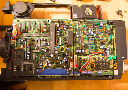
There were four large circuit boards, two on each side, and many more smaller boards along the front, bottom, back and top of the camera. Every single one was entirely composed of hand-soldered, through-hole components (surface-mount technology didn’t take off until the late 80s). Separating the boards from the case and from each other was quite straightforward:
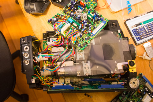
Underneath the circuit boards, and making up the vast majority of the camera’s internal volume, was the optical system which focuses, splits, and detects the light seen by the camera:
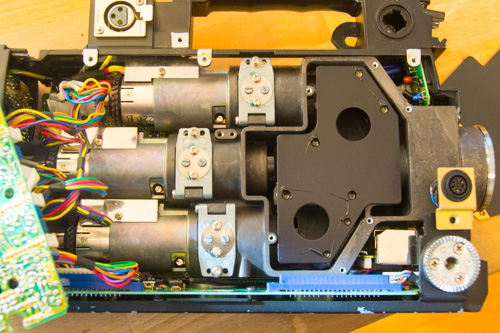
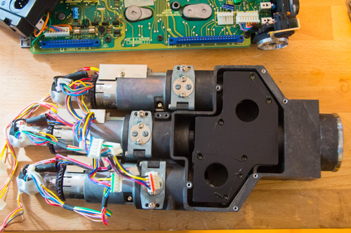
With a few more screws and electrical connectors removed, I was able to extract the whole optical assembly:
I actually knew next to nothing about video camera technology from this era, so I was thrilled to see what was going on inside. Removing the protective black plate revealed the heart of the camera’s optics:
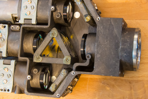
Now we can see what’s going on, and understand why it had to be that way. Light enters from the right side of the device, and then strikes the triangular beam splitter near the center of the image. That triangular mount contains two tinted lenses: the first reflects blue light up to the top lens on the left side while allowing red and green to pass through; the second tinted lens reflects red light down to the the bottom left lens and allows green to pass through to the middle left lens. The three lenses on the left side lead to three video tubes, the long silver cylinders shown in the previous image. Each tube is held in place under one of the three silver hatches shown above. Opening one hatch reveals a very clever mechanism:
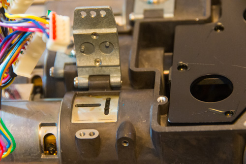
The two slots in a sideways T shape fit around the two pegs on the bottom of the hatch. The pegs are connected to screw heads on the outside of the hatch, so turning one screw will precisely adjust the orientation of the video tube, and turning the other will adjust its distance from the lenses (and thus its focus).
Here are the video tubes after being removed from the camera:
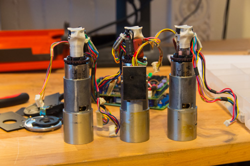
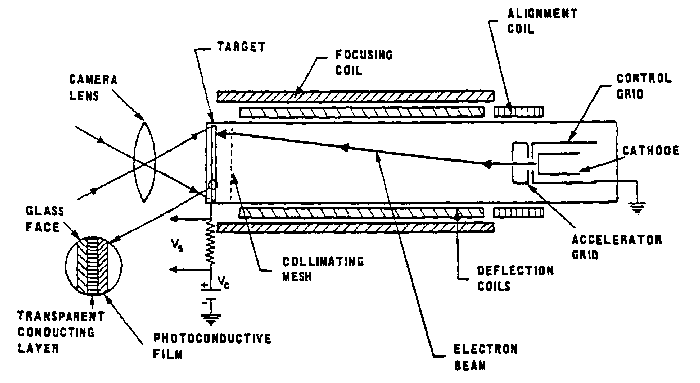
According to hdwarrior, these are Saticon tubes, which consist of a photoconductive screen, and an electron gun. Here’s a diagram from Wikipedia of a similar device:
Each video tube consists of a photoconductive screen, onto which the image is focused. A beam of electrons is emitted from the cathode at the other end of the tube, and it is focused onto a single point on the screen by a set of electromagnets. The screen is “photoconductive” because it becomes more conductive to electricity when exposed to light. This means that, by connecting an electrode to the screen and measuring the amount of current which results from the electron beam striking the screen, we can determine exactly how much light is shining on the precise point on the screen where the electron beam is focused. By moving the electron beam across the screen, we can then determine the amount of light at every point on the screen, which means that we can reconstruct the image that was focused onto the screen.
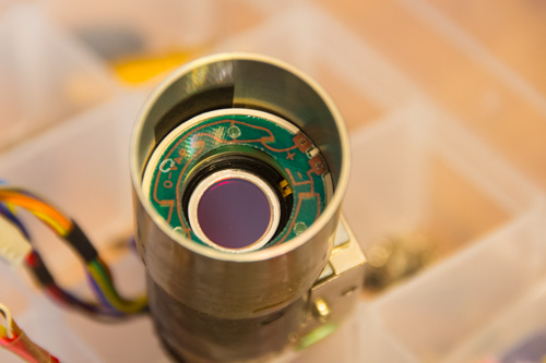
Here’s the photoconductive screen of one of the tubes in my camera:
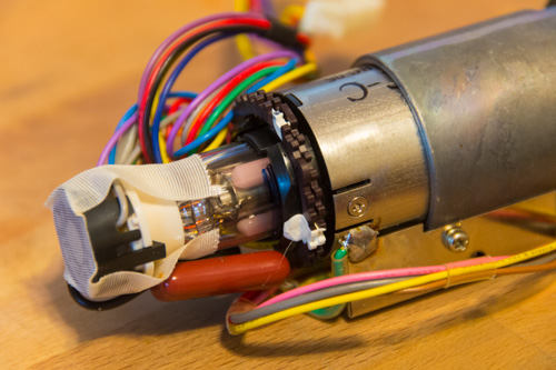
And here’s the cathode from the same tube:
The astute reader may realize that at no point in this discussion of the video tube has any notion of color come up. The tube itself appears to have no way of determining the color of the light at any given point in the image, only its intensity. This explains why the camera needs its complex and beautiful beam splitter to divide the light into its red, green, and blue components so that each color can be independently measured by the three video tubes.
Playing with Light
The final step in exploring this camera was to play around with the colored mirrors and lenses of the beam splitter. Removing all three video tubes revealed three sets of lenses with colored filters:
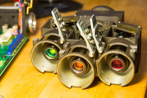
Although the filters in the above image appear to be green, orange, and red, this is actually an effect of the particular angle of the light reflecting off of them. They actually transmit only blue, green, and red light, respectively. We can easily see this by pointing the other end of the camera at a well-lit scene:
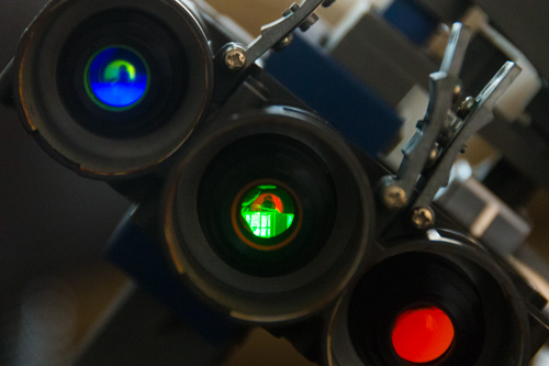
The three colors are rendered at radically different magnifications, as we can see by pointing them at the same scene:
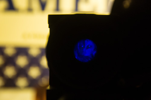
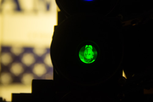
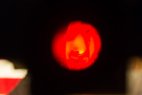
But, presumably, the specific arrangement of the video tubes compensates for this and allows the camera to perceive the separate red, green, and blue components of the same scene.
Conclusion
Taking apart this camera was fabulously fun, even if I couldn’t get the viewfinder working. Electronics from this era are extremely accessible, and the optics are lots of fun to play around with. Hopefully, I’ll be able to return to some of the components I dissected at a later date and find more fun things to do with them.
Robin Deits 07 February 2014