More Microscope, or How not to Build a Linear Bearing
Recently, I had the chance to turn an old TV camera lens into a reasonably powerful microscope system. The setup I built was fun to play with, but it was almost impossible to use, and I ended up with a large collection of out-of-focus or blurry images. The main reason for the problems I had was nothing to do with the optics of the microscope, but with the mechanical setup I used to hold the camera and the sample I was photographing. Here’s a diagram of the setup I was using:

The camera is mounted to a tripod sitting on a table, and the sample stage is just an aluminum plate with three screws (two are shown in the diagram) to adjust its height and focus the image. This worked…sort of. The obvious problem with this setup was that the mechanical path from the sample to the business end of the lens was extremely long and relatively flexible (especially the tripod mount). This meant that I had no stability against vibration, since any movement of the table, microscope, sample stage, or camera would blur the image. In fact, I had to set the camera on a timer and then leave the room in order to take an image, since the vibration caused by standing near the setup would disrupt the image.
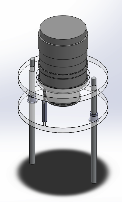
To improve the situation, I decided to hang the sample stage from the end of the lens, making as direct a connection as possible between the sample and the lens, while still allowing the stage to move up and down for focus. The design I came up with was something like this:

For the actual implementation, I replaced the three adjustment screws with a single screw and two aluminum rods inside nylon bushings. Here’s the design, rendered in SolidWorks:
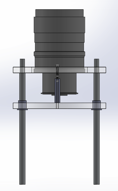
So, did it work? Er, no. The vibration problem was almost completely solved, since the springiness of the tripod was now isolating the setup from external vibration instead of amplifying it, but turning the screw to move the stage up or down was almost impossible. Any mechanical engineering student can probably tell you exactly why, and it has to do with the way I arranged the vertical slide mechanism.
How not to build a linear bearing
A linear bearing is just the general term for something that allows a part to move along a single line, but not to move in any other direction. You can create a simple one by putting a rod through a plastic bushing, as I did. This will work fine until you start putting a load on the system. Let’s look at a cross-section of a bushing like the one in my microscope stage:

Now let’s apply a load on the left side of the sample stage (where the adjustment screw might be mounted:

The green arrow is the external load, and the red arrows on the right show the reaction forces from the collision between the corners of the bushing and the aluminum rod. They’re much larger than the load force on the left because they have a much shorter lever arm but still need to produce an equal and opposite torque to cancel the load torque.
The result in my microscope stage was that these reaction forces were so large that they created enough friction to completely prevent the stage from moving, which made focusing impossible.
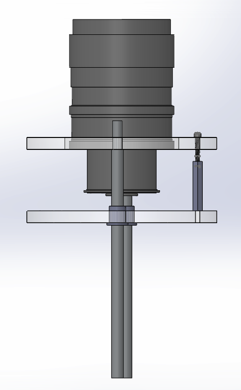
We can fix this by trying to move the reaction forces apart, increasing their leverage and thus decreasing the magnitude required to cancel the load torque. We might do this by mounting another bushing lower down on the rod:

This was exactly what I did for the final revision of the microscope stage, seen here in real life:
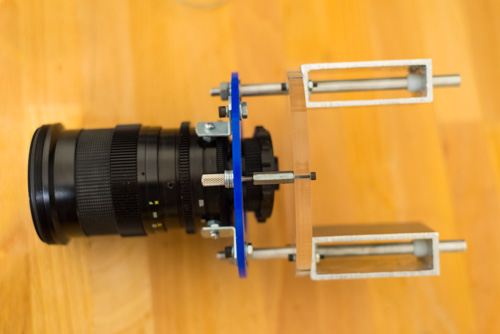
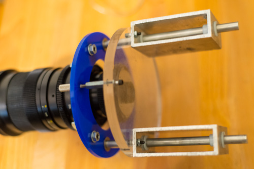
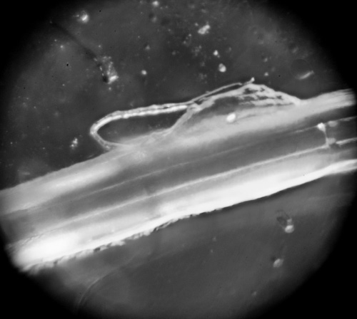
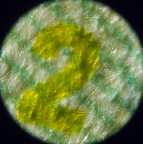
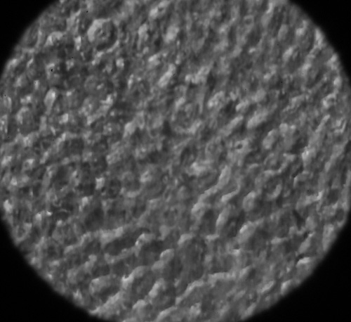
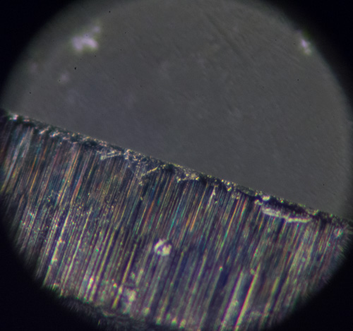
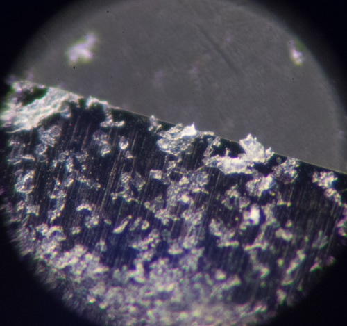
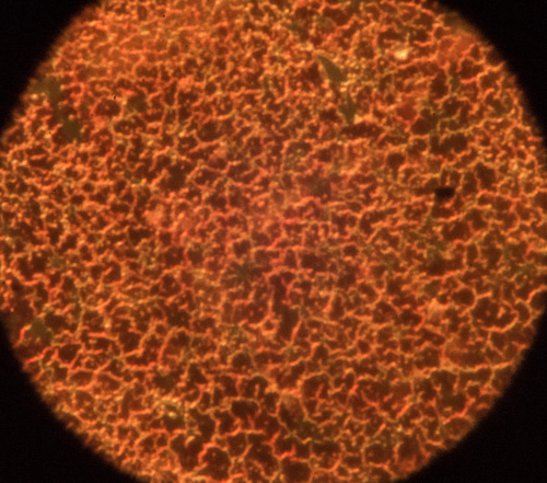
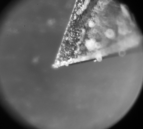
So, did it work? Yes (mostly)! The focus is still a bit sticky, but it works well enough, and I got some lovely images out.
Results
Conclusion
There’s certainly a lot that I could do to improve my microscope stage, but I think that I’m mostly limited by the quality of the optics now, so there’s not much point. Next, I’ll be using the microscope to find the correct cutting tool for making scratch holograms.
Robin Deits 27 September 2013