Programmable Holograms
In my previous two posts on abrasion (scratch) holography, I focused on creating the holograms by scratching circular arcs into plastic. This is easy to do by hand, and can even be automated by a CNC milling machine, but it is still entirely limited to static images which take a long time to produce.
The ideal platform for this would be a reusable display which can create the same directed-light effects as the scratches without being scratched. How could this be done? Well, I haven’t solved the problem yet, but I’m going to spend this post talking about a potential solution using hardware that already exists inside your TV.
The fundamental technology that we’ll be looking at is called a Digital Micromirror Device or DMD for short. It’s the technology that powers modern DLP TVs and projectors, and it allows for excellent contrast and extremely large displays, among other advantages. The DMD chip consists of an array of thousands or millions of microscopic aluminum mirrors, each of which can be individually tilted to two different angles.
#Background on DLP The basic principle of DLP can be seen in this pair of cartoons:

A DLP micromirror chip, with one mirror “on” and one “off”.

A DLP micromirror chip, with both mirrors in the “on” state.
When the mirror is tilted in the “on” state, it reflects light from the lamp onto a single spot on the screen, lighting up the pixel at which it is pointing. When the mirror is tilted the other way, it reflects the light away from the screen, turning that screen pixel “off”. By doing this for each of the millions of mirrors in the chip, we can turn on or off each pixel of our TV or projector.
##Color in DLP This technique, however, raises some pretty thorny problems. First of all, how do we control the color of each pixel? The way most types of display solve this problem is by having groups of red, green, and blue pixels next to each other, so that we can turn each of them on or off to get the right mix of colors. But with DLP, every mirror just reflects the white light of the lamp to the screen.
DLP displays get around this by rapidly switching the effective color of the lamp. This can either be done with a set of red, green, and blue LED lamps which are turned on and off in quick succession, or with a spinning wheel with red, green, and blue-tinted windows placed right in front of the lamp. The chip then draws the “red” part of each frame of video while the lamp is shining red, then draws the “green” part of the image while the lamp is green, and so on. Since red, green, and blue are the primary additive colors, we can create just about any color we’re likely to want using this combination.
The second problem inherent in DLP displays (and which will be very relevant in my discussion of DLP holograms) is that each mirror has only the two states, “on” and “off”. There is no gray area, which means that each of our pixels can only be completely bright or completely dark at any given time. Unless we can get around this, our DLP display will only be able to produce a handful of colors (bright red, bright green, bright white, black, etc.).
The brightness problem is solved through rapid switching: Instead of varying how bright each pixel is, we instead vary how often that pixel is turned on. For example, if we switch a given pixel on and off 10,000 times per second, your eye will not be able to see the switching, and will just see a constant brightness (for comparison, a movie in a theater changes frames just 24 times per second and your eye can barely detect the flickering from that). However, if the pixel is on, say, 75% of the time, then you will see it as being brighter than if it were on for only 25% of the time. So, by varying how often the pixel is turned all the way on, we can smoothly vary how bright it appears to be, and thus create all the shades and colors we want.
#Using a DLP Chip to Create Holograms The micromirror chip’s ability to control the direction of reflected light makes it extremely interesting as a holographic display device. To create a holographic effect, we must use the angled mirrors to direct some of our source light to the right eye and some to the left, so that each eye sees a different image. For example, if we had two mirrors and a single light source, we could create the illusion of a single point hovering below the mirrors:

This is cool, but it introduces several problems we need to solve, which I’ll approach now.
Problem 1: Seeing All the Mirrors
The first issue is that this will work perfectly for a point light source (a ideal light source with no width, like a flashlight with an infinitely tiny opening), as long as we have exactly two mirrors. If we have more than two mirrors, the light from some of the mirrors won’t make it to either eye, like so:

See how the ray from the leftmost mirror just goes off into space? That’s a problem. The solution to this is to use a wide light source. We’ll still treat our mirrors as infinitely tiny (they’re only a few micrometers across in a real DLP chip, so this is a good approximation), but we’ll make our lamp much bigger, perhaps more like the size of a long fluorescent tube. This means that each mirror will create a wide beam of reflected light, like so:

(Actually, the light from the lamp goes off in all directions, rather than being focused onto the mirror. But, since none of the light that isn’t directed at the mirror gets reflected, we will ignore it for now).
If we figure out the right size and distance for the lamp, we can ensure that the reflected beams from our mirrors have some overlap. For example, with two mirrors set up like this:

we create a region of overlap between the beams of light (indicated by the arrow). If we put an eye or camera in that region, it will see light reflected from both mirrors.
This seems great in theory, but can it work in practice? To find out, we need to work out the math for a wide light source and tiny mirrors and then plug in some reasonable values. This is what our setup looks like:

We have a lamp of width \(2 w_1 \) and a DLP chip of width \(2 w_2\). The lamp is a distance \(d\) above the chip. One eye is located at point E, \(y_e\) above the chip and \(x_e\) away from the centerline of the lamp and chip. A single ray of light is emitted from a point \(x_1\) along the width of the lamp and reflects off a mirror at a distance \(x_2\) from the center of the chip. The ray of light ends at a distance \(x_3\) from the centerline. By varying \(x_1\) and \(x_2\), we can consider light from any point on the lamp reflecting off any point on the chip.
We’ll call the angle of incidence of the ray \(\phi_1\) and the angle of reflection \(\phi_2\), and we’ll assume that each mirror can lie at \(\pm \theta \) from the horizontal. That means that
\[
\phi_2 = 2 \theta - \phi_1
\]
assuming counterclockwise is positive for all our angles. From the definition of the tangent, we can find that
\[
\tan{\phi_1} = \frac{x_2 - x_1}{d} \\
\tan{\phi_2} = \frac{x_3 - x_2}{y_e}
\]
Therefore
\[
\tan{2 \theta - \phi_1} = \frac{x_3 - x_2}{y_e}
\]
The angle difference formula for tangent lets us rewrite this as
\[
\frac{\tan{(2 \theta)} - \tan{\phi_1}}{1 + \tan{(2 \theta)} \tan{\phi_1}} = \frac{x_3 - x_2}{y_e} \\
\frac{\tan{(2 \theta)} - \frac{x_2 - x_1}{d}}{1 + \tan{(2 \theta)} \left(\frac{x_2 - x_1}{d}\right)} = \frac{x_3 - x_2}{y_e} \\
x_3 = y_e \left( \frac{\tan{(2 \theta)} - \frac{x_2 - x_1}{d}}{1 + \tan{(2 \theta)} \left(\frac{x_2 - x_1}{d}\right)} \right) + x_2
\]
What does this mean? Well, let’s examine these variables again. The eye at point E will see the light ray if and only if \(x_3 = x_e\), so this is our ultimate goal. If we keep the observer’s head stationary and centered, then \(x_e\) is fixed as exactly half the distance between the viewer’s eyes. Likewise, \(y_e\) is fixed as the viewer’s height above the chip, and \(d\) is fixed as the distance from the lamp to the chip. We want every mirror on the DLP chip to reflect light to the eye when it’s turned ‘on’, but not when it’s turned ‘off’. If our mirror tilt angle is \(\pm 10^o\), then when \(\theta = 10^o\), then there needs to be some point along the lamp \(x_1\) for each point on the chip \(x_2\) such that \(x_3 = x_e\). And when \(\theta=-10^o\), there should be no point \(x_1\) for any \(x_2\) such that \(x_3 = x_e\).
By symmetry, if this is true for the right eye, then it should also work for the left eye, with the values of \(\theta\) reversed.
This is hard to wrap your head around (or, at least it was for me), so we’re going to show this graphically. If we felt like being clever, we could probably simplify the equation further, but at this point it’s easier to just start plugging it into Python. Using the excellent IPython notebook mode, I chose some sensible values for our variables, as follows:
\(w_1\): 0.7 meters (reasonable for a mid-size fluorescent tube)\(w_2\): 0.0127 meters (assuming a 1-inch wide chip)\(x_e\): 0.0315 meters (source)\(d\): 2 meters\(y_e\): 0.3 meters (a viewing distance of about 1 foot)\(\theta\):\(\pm 10\)degrees (typical for a DMD chip)
You can see the results in the following graph:
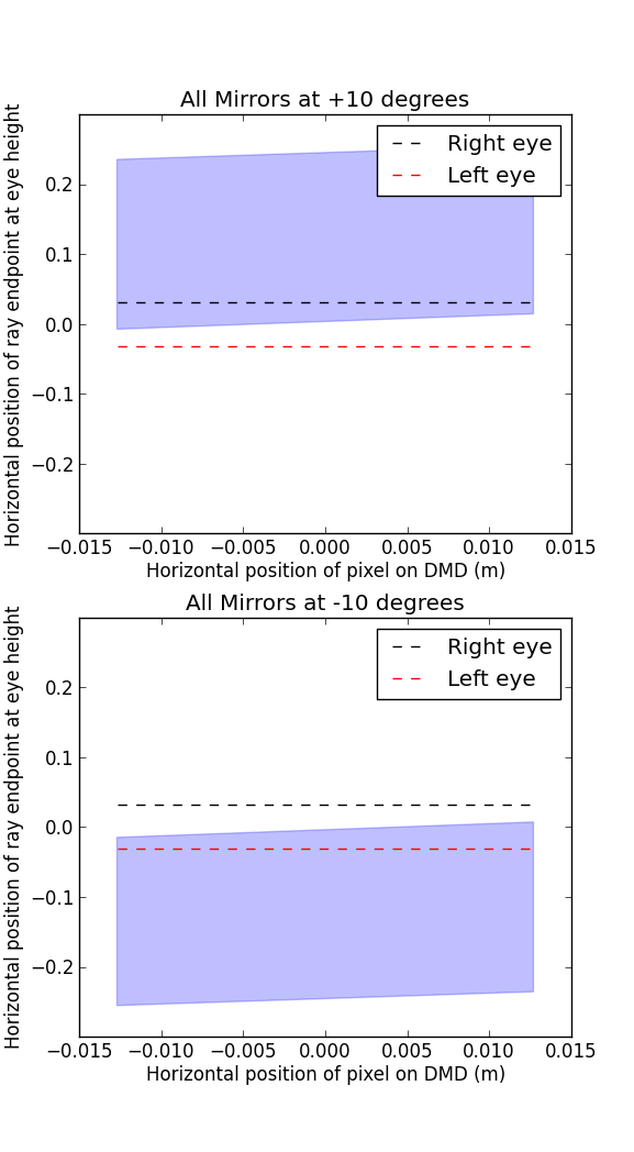
The x-axis shows \(x_2\) and the y-axis shows \(x_3\). The shaded blue region is all the values for \(x_3\) for all possible values of \(x_1\) between \(-w_1\) and \(w_1\). And the two dashed lines are the right and left eyes, located at \(x_e\) and \(-x_e\), respectively. The difference between the top and bottom graph is just the mirror angle \(\theta\) being switched between \(+10^o\) and \(-10^o\).
What this means is that when the mirrors are set to \(+10^o\), the right eye will see reflection from all the mirrors on the chip, and the left will see none. Likewise, when the mirrors are set to \(-10^o\), the left eye will see reflection from all mirrors and the right will see none. This is exactly what we wanted!
Problem 2: Turning Pixels Off
You may have already noticed that our wide light source solution has created a new problem: we can’t actually turn pixels off. Since each mirror has only two states, \(+10^o\) and \(-10^o\), and each state corresponds to one eye seeing reflection from the mirror, there’s no state for any mirror which results in neither eye seeing it. This makes our display nearly useless.
However, there’s a (sort of) solution to this as well. Remember from the beginning of this post when I talked about how dimming is done with a normal DLP display? The mirror is toggled rapidly between its on and off state to create the illusion of being partially on. We can use the same trick here: to turn a pixel ‘off’, we just switch rapidly between its left and right states, which makes it appear to be at half brightness to each eye. This limits our contrast ratio (the brightness of an ‘on’ pixel divided by the brightness of an ‘off’ pixel) to 2:1, which is pretty lousy, but it does solve the problem.
Conclusion
Now we can display pixels to just the right eye, just the left eye, or turn them off at will. This is the essence of a 3D display, and one that doesn’t even require glasses! It does, however, have a few lingring issues:
- The display is tiny (about an inch across)
-
There is only one possible depth value, since the mirror angles are fixed. So, we can't create 3D shapes, we can just display flat objects in a 3D space.This is incorrect, as I explain in a later post
- The viewer can’t move her head more than an inch or two without completely ruining the effect.
Ah well, nobody’s perfect…
If you’re interested, you can download the IPython Notebook I used to make this graph from my ScratchHolograms github repository.
Robin Deits 20 May 2012