My Dad's New Lights

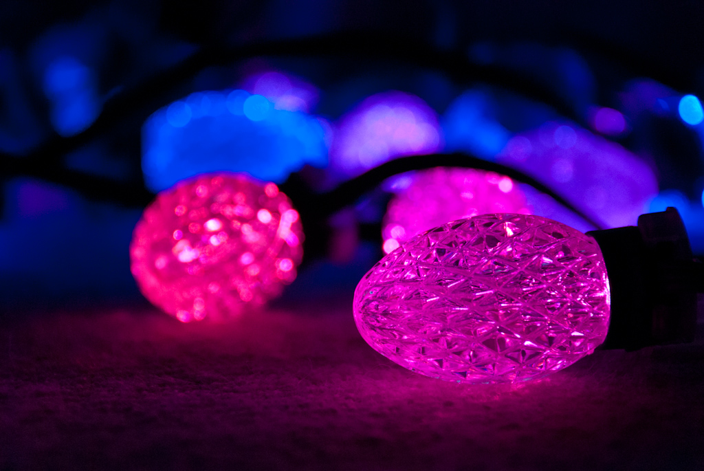
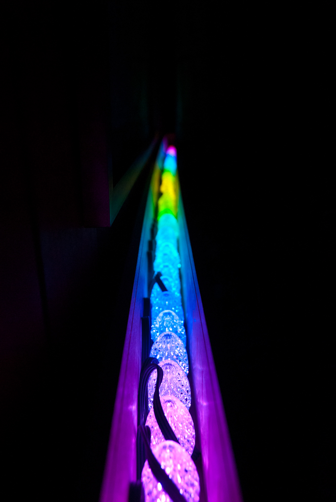
The finished product.
Background
Last January, my crazy MIT (East Campus, 1E) friends and I designed and built a 1,300 LED programmable lighting display for our hallway. That’s a post for another day, but my friend Ciuffo (of ch00ftech.com fame) put together a fantastic video of the construction:
Naturally, I wanted my own system for my apartment. But, since the original cost about $1000 and took the combined force of a dozen MIT students to produce, I figured re-implementing the hardware wasn’t a good idea. Fortunately, darco of deepdarc.com reverse-engineered the communication protocol for the GE Color Effects LED Christmas lights, which provided me with a reasonably cheap set of hackable hardware. I took some of his software and adapted it to be compatible with the control code for our hallway lights. The result is a fully-programmable LED light string with easily customized, animated patterns for my very own room, all for less than $150. Software and hardware links are at the end.
Building lights for my dad
When Christmas came around this was the obvious gift for my dad, who I knew would love to have a new toy to play with. I bought another string of GE lights and an Arduino Uno to control them. My dad, though, had the brilliant idea of a father-son adventure constructing a tasteful case for the lights (they did look a bit tacky on their own). And so began the adventure, documented here:
 Verifying that the lights and the micro work. Looks pretty good so far.
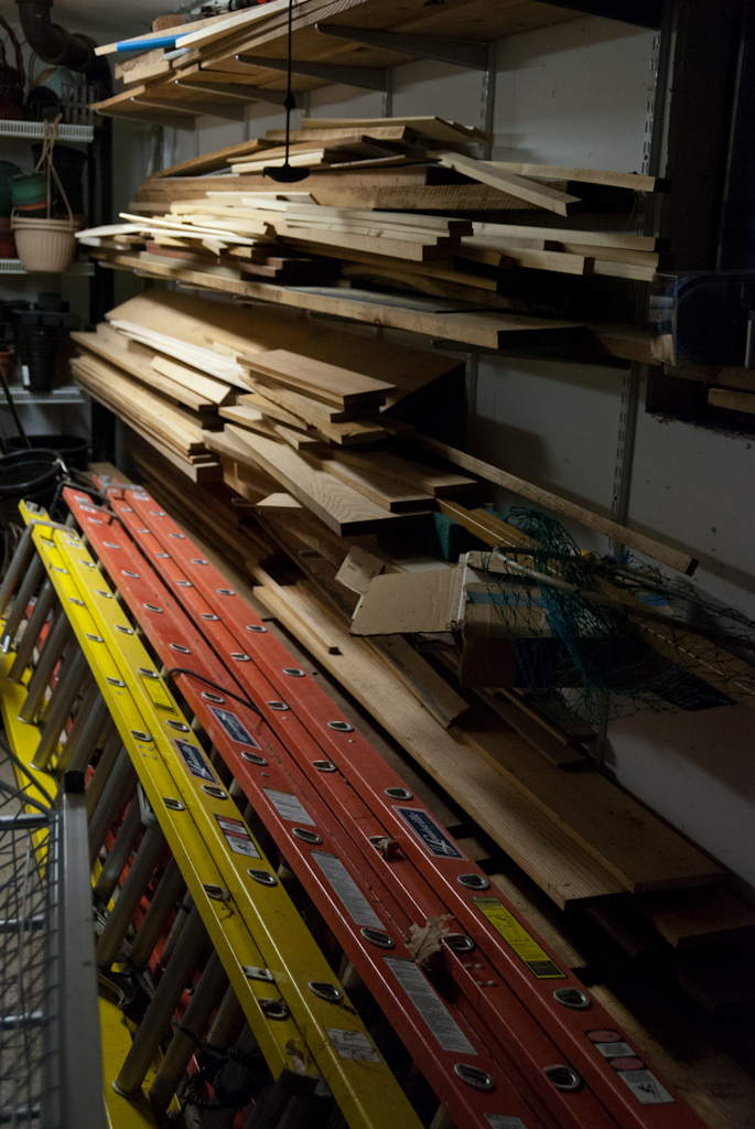 My dad’s wood collection. Shockingly, he didn’t have the piece we needed, so we picked up a couple of poplar boards at Home Depot.
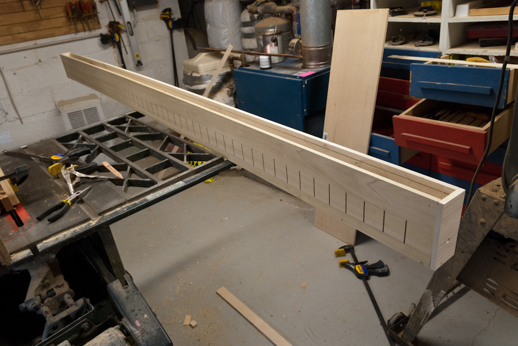
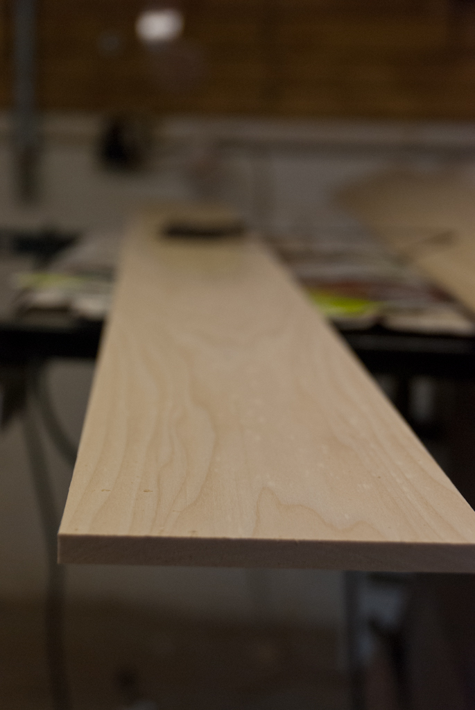 The front panel board, sanded and planed.
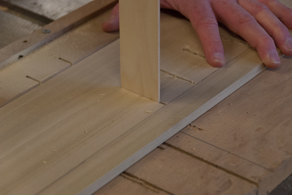 We set up a simple jig to cut a small slit in front of every light in the front panel using the table saw. The vertical piece sticks through the last slit into the jig underneath, and the saw blade rises from below to make the cut.
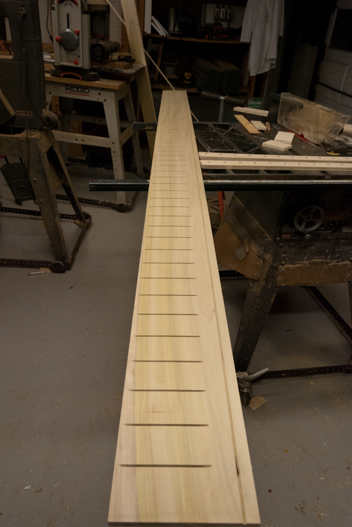 All 50 slots cut into the front panel.
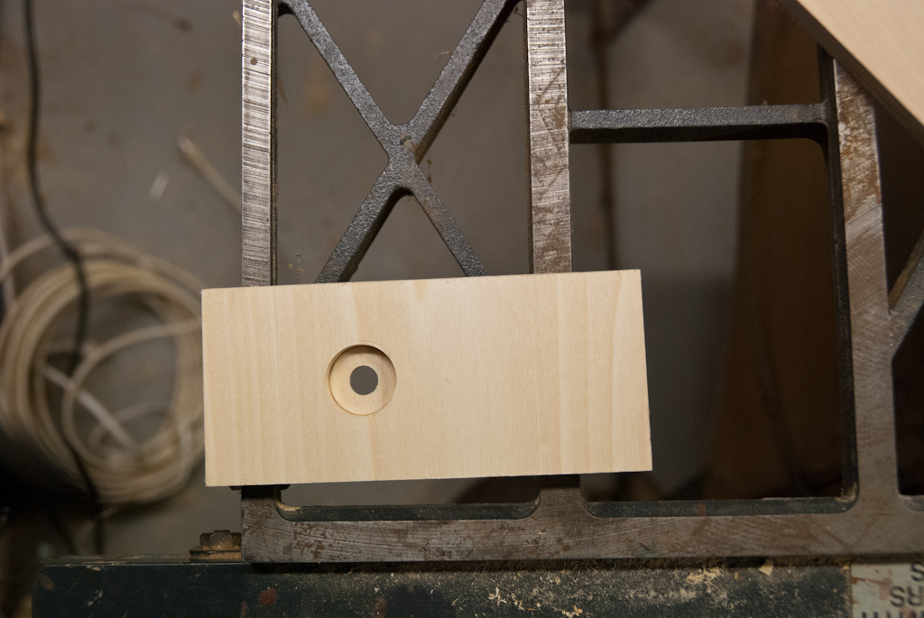 The end cap with a countersunk hole for the 1/4” audio jack I used to send power and data to the lights. This may have been a very poor choice, for reasons which will come up later.
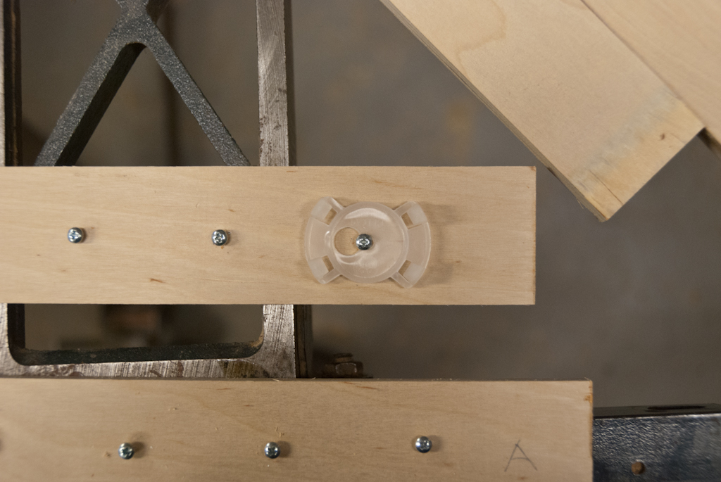 Here’s the bottom of the box, with small sheet metal screws at intervals spaced just a bit wider than the lights themselves. The plastic clips (one shown) that the lights come with fit directly over those screws.
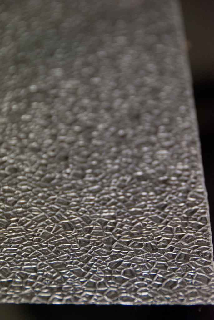 We had intended to use this stuff, the acrylic sheet used in fluorescent light fixtures, to cover the top of the box and diffuse the light…
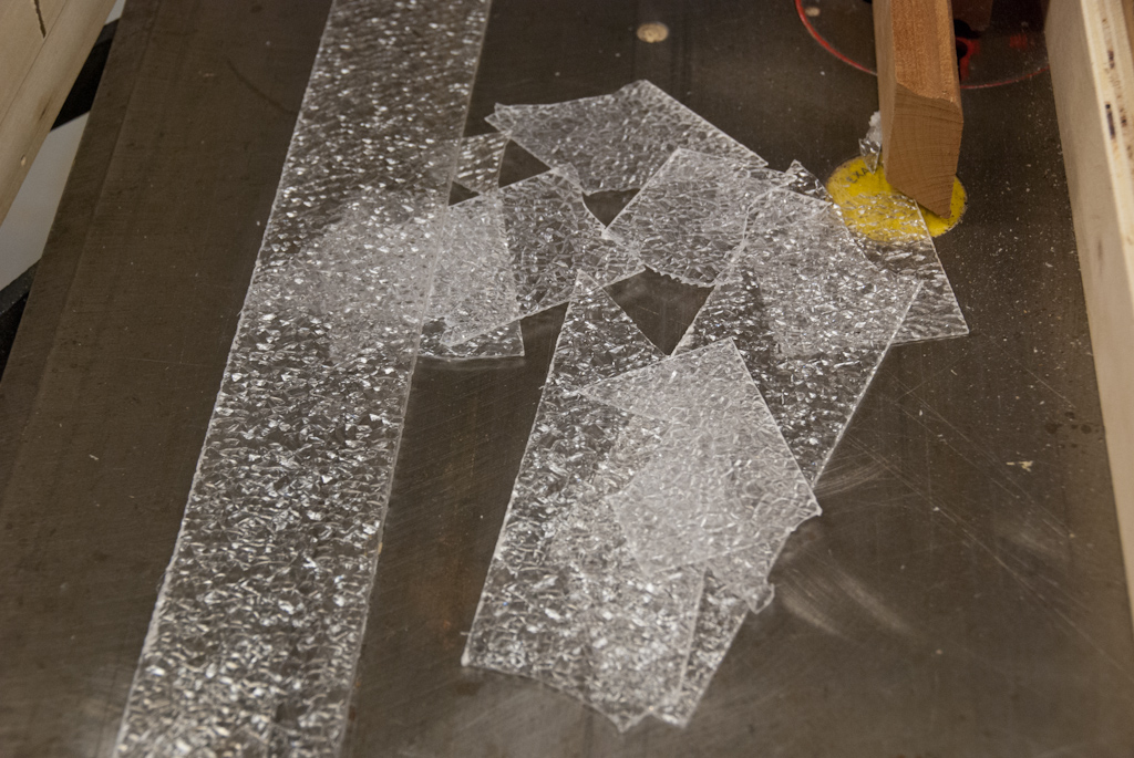 …but cutting it turned out to be more trouble than it was worth, so we scrapped that idea and just left the top open.
 The light box, fully assembled.
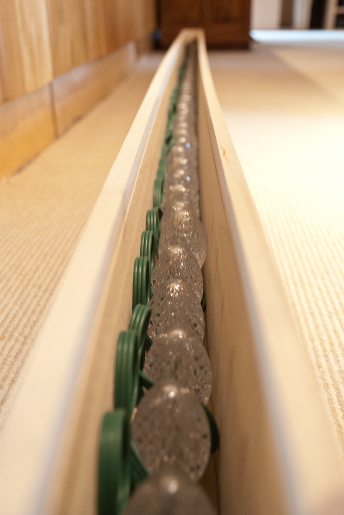 After installing the lights (they just barely fit along with their wires).
 Testing the lights. They worked fabulously, but only after I spliced out the first light. I think it may have been damaged by a short circuit when I unplugged the power cable.
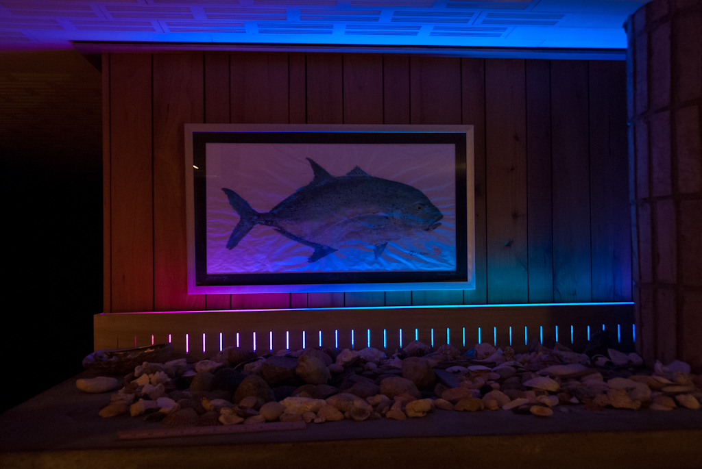
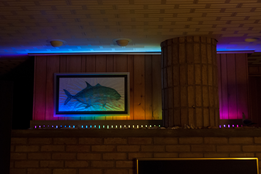 The results, in place.
Lessons learned about power connectors
I spent a while thinking about the best way to bring power and data to the lights from their controller box. The requirements for the connection were (in no particular order):
- It should have exactly 3 conductors
- It should be easy to plug and unplug
- It should be easy for my dad to get or make a longer cable if he moves the lights or control box
- It should look good
My first (incredibly bad) idea was to use a 3-prong power cable. This had a lot of advantages: it had the right number of conductors, would be easy to use, and would allow the user to extend the reach of the cable with standard extension cords. Unfortunately, it would also allow an unwary user to accidentally plug his USB port into a 120V wall socket, which would be extremely bad.
After much debate, I settled on 1/4 inch audio cable from monoprice. This looked fantastic, would be easy to buy in longer lengths if necessary, and had jacks which were easy to install into my control box. Unfortunately, I failed to think of one problem: the design of the cable is such that when plugging in the cable the third conductor (the one at the very tip) touches the contact for the first conductor in the jack. This means that if the circuit is powered when the cable is plugged in, we can end up with a short or an inverse voltage being supplied to the lights. I believe this is what temporarily killed the entire strand of lights while I was testing. Fortunately, the cure to this failure was fairly simple: since the lights are entirely modular, I saved the day by cutting the first light out:
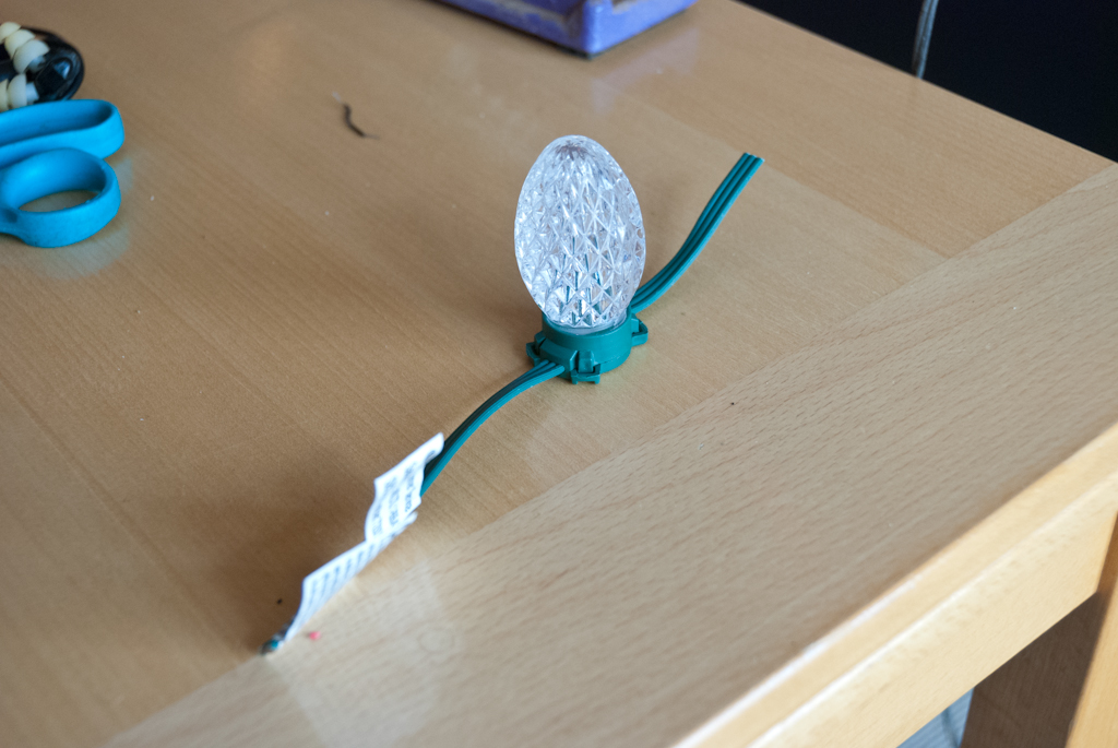 The dead light, after removal.
After that, I made sure to turn off everything before connecting any cables, and no further problems were had.
Building your own
This is definitely a very doable project if you’re interested in making your own set. Darco’s hacking instructions are at deepdarc.com, but the only hardware modifications to the lights that were necessary were cutting off the original control box and connecting a data line from an Arduino board. The software I used is at github.com/mboyd/Bemis-100 under Firmware/ge_arduino, all running on an Arduino Uno. The lights I bought are here on amazon but are currently unavailable. However, these “Multi Function GE Christmas Lights” look like the same product, but it’s hard to be sure. Also, Costco was carrying the lights last Christmas season, and they may have them again this year. Happy hacking!
Update: June 6th, 2012
My dad decided to do a little more work on the lights. Here’s his description:
I decided that having the lights and cords visible meant more work was needed. Fortunately, I was able to find some 0.05” polystyrene at Home Depot that, if carefully cut for width, could be inserted in the channel we had previously cut for the highly unsuccessful fluorescent light diffuser plastic. Finding that thickness was key, because some 0.08” acrylic I had was too thick to be inserted on the diagonal and still leave enough width to slot securely in the track on both sides. It would have been nice to have some bigger stock, but I had to make do with 10” long pieces. I scuffed it up on both sides with my random orbit sander and 220 grit sandpaper, which made it nicely frosty. The fitting was pretty straightforward except at the plug end I had to do a touch of trimming. I cut a 1” diameter half circle in the end of the final piece so I could get it out again if needed - clever to have figured that out before permanently sealing the apparatus. I have attached a couple of pictures of the finished product. I did some testing and convinced myself that the diffuser didn’t significantly affect the light output on the wall behind the unit, so I figure it’s a win all around.
Here are his results:
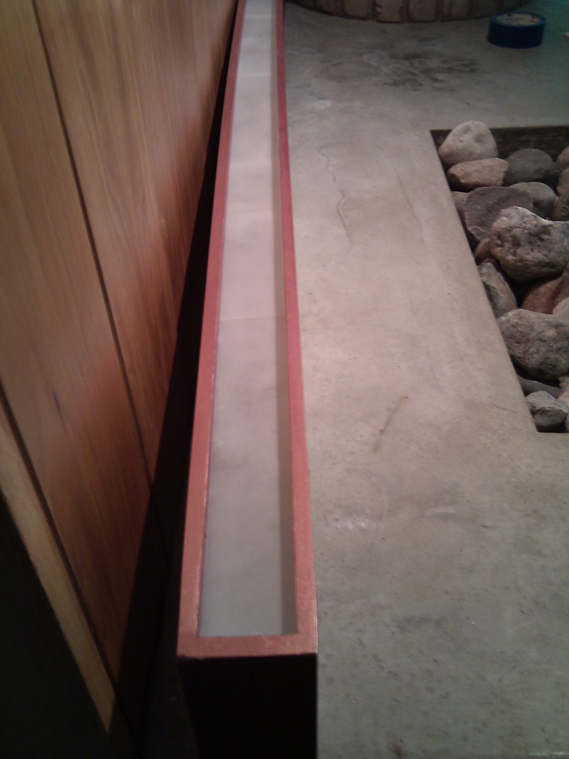
The light box, with the diffuser installed.
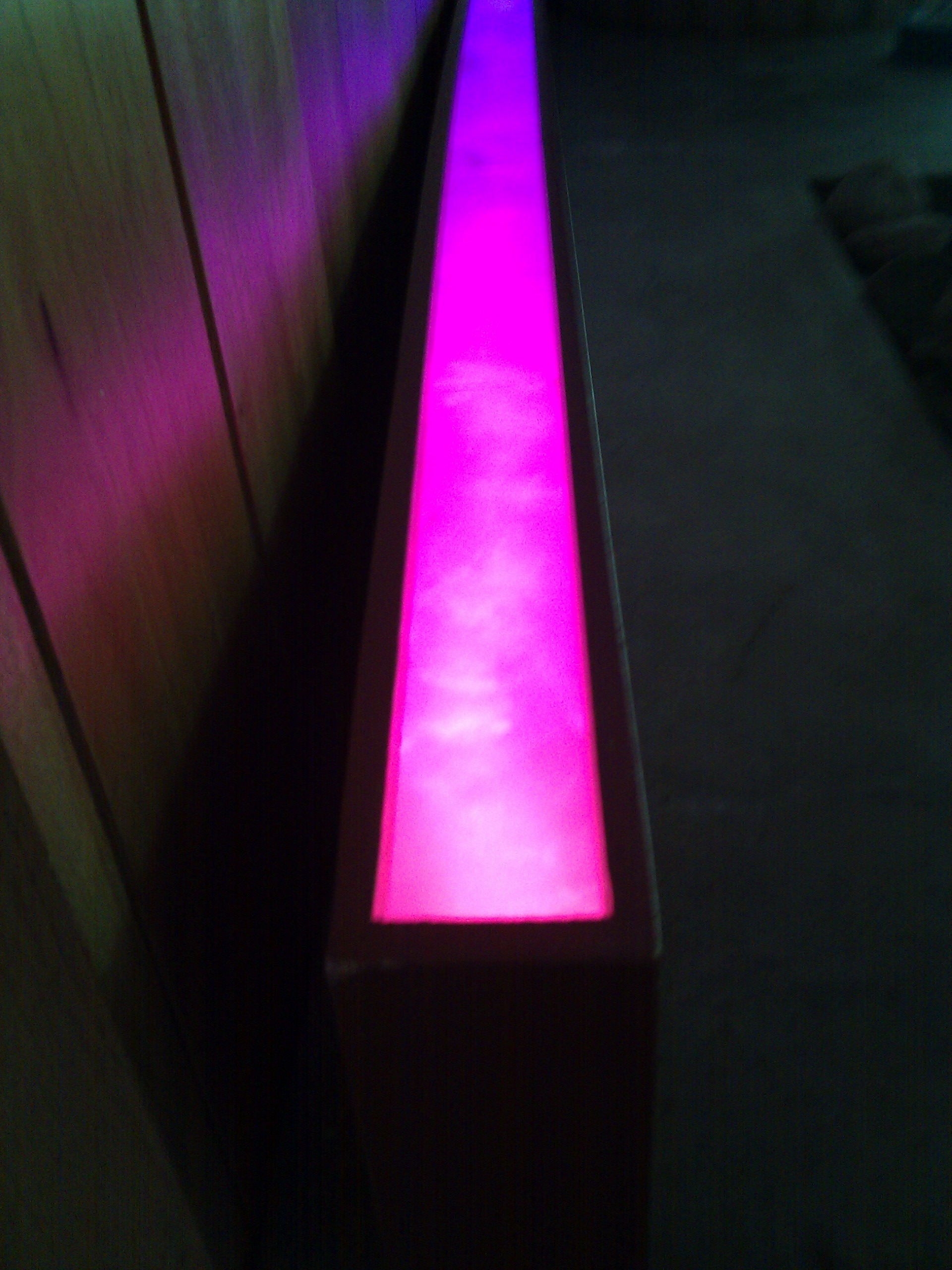
And the final product.
Update: July 26, 2014
I’ve upgraded and simplified the electronics driving the lights. You can read all about it in Christmas Lights 2: Serial Protocol Adventures.
Robin Deits 23 April 2012